Categories
Latest Updates
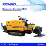
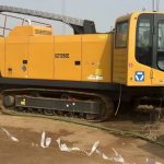
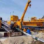
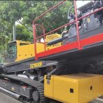
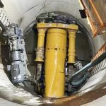
Directional drilling through construction will not hinder traffic, will not destroy green space, vegetation, will not affect shops, damage and adverse effects on traffic, environment, surrounding building foundations. There is no water or underwater operation, it does not affect the navigation of the river, does not damage the dykes and riverbed structures on both sides of the river, and the construction is not limited by seasons. It has the characteristics of short construction period, few personnel, high success rate, and safe and reliable construction. It is easy to adjust the laying direction and burial depth, the arc laying distance of the pipeline is long, and the pipeline can bypass the underground obstacles. The buried depth of directional drilling is generally less than three meters. When crossing the river, it is generally buried at a depth of 7-18 meters under the riverbed. There is very little oxygen and other corrosive substances in the stratum, so it plays the role of natural anti-corrosion and heat preservation. Compared with other construction methods, the speed of entering and leaving the site is fast, the construction site can be adjusted flexibly, especially in complex construction, it can fully demonstrate its advantages, and the construction occupies less land, the project cost is low, and the construction speed is fast.
The directional drilling crossing construction process is generally divided into two stages: the first stage is to drill a pilot hole according to the design curve route; the second stage is to ream the pilot hole and drag the pipeline back to the pilot hole along the enlarged pilot hole. In the hole, complete the pipeline crossing work.
details as follows:
2.1 Prefabrication of steel pipes: at about 5m away from the excavation point where the directional drilling passes through, the prefabricated pipes are laid out, and the length is about 3-5m longer than the design length. After welding, after passing the appearance and non-destructive testing, the pressure resistance and tightness are carried out according to the requirements of the specification. test. Welding joint anti-corrosion shall be carried out one week before the directional drill is passed through and dragged back, and electric spark anti-corrosion and leakage detection shall be carried out on the prefabricated pipeline, and placed on the roller bracket for standby.
Only when it is limited by the pipe layout site, the two-to-one or multiple-to-one pipe layout method can be used, that is, two rows and multiple rows of finished pipes are arranged in parallel.
2.2 Drilling pilot holes: The drilling rig is installed on the side of the entry point, and the appropriate drill bit and guide plate or underground mud motor should be selected according to the geological conditions to be crossed. The drill bit rotates) to cut the formation, and the drilling direction of the drill bit is continuously advanced, measured and adjusted to ensure that the completed pilot hole curve meets the design requirements.
2.3 Pre-reaming and dragging of prefabricated pipelines: In general, when the diameter is greater than 200 mm, pre-reaming is required, and the diameter and times of pre-reaming are determined according to the specific drilling rig model and geological conditions. Since in the stage of drilling the pilot hole, the drilled hole is often smaller than the diameter of the return pipeline. In order to make the drilled hole diameter reach 1.3 to 1.5 times the diameter of the return pipeline, it is necessary to use a reamer to guide from the excavation point to the soil entry point. The hole is enlarged to the required diameter.
2.4 Back-hauling prefabricated pipeline: After the underground hole is pre-reamed and meets the back-hauling requirements, connect the drill pipe, reamer, back-hauling joint and installed pipeline in sequence, and start back-hauling operation, which is driven by the drilling rig turntable The drill pipe rotates and retreats to carry out reaming and dragging. Since the enlarged hole is filled with mud, the product pipeline is in a suspended state in the enlarged hole, and the surrounding of the pipe wall and the hole is lubricated by the mud, which reduces the backflow. The drag resistance also protects the anti-corrosion layer of the pipeline. After multiple pre-reaming by the drilling rig, the final hole diameter is generally 1.5 times larger than the diameter of the pipe, which generally does not damage the anti-corrosion layer.
“Add one more” back-drag directional drilling crossing means that when the back-drag of the first row of finished pipes is connected end-to-end with the second finished pipe, the back-drag is suspended, and the back-drag of the first row of prefabricated pipes and the second row of pre-fabricated pipes are welded without damage. Inspection and anti-corrosion repair, and then continue to drag back, and so on, drag the pipeline back to the entry point. Because the “multiple-connected” back-towing directional drill can generally stay within 5 hours, the welding time is the longest in these 5 hours. If the welding quality is unqualified and repaired, it will affect the pipeline. The success rate of back towing is also the risk of “adding one more” to directional drilling.
3.1 The difference between the whole directional drilling traversal and the “multiple-by-one” back-drag directional drilling traversing
3.1.1 The difference between processes
whole directional drill
3.1.2 Differences in construction methods
In the construction process of directional drilling “multi-connection” and the overall dragging of directional drilling, two (several) sections of pipe layout, midway welding, non-destructive testing and anti-corrosion repair are added. Among them, two sections of pipe layout and halfway welding of pipes are the most critical steps, reflecting the connotation of “multiple connections”. In addition to the characteristics of the entire directional drill crossing, the “multiple-connected” back-towing directional drilling mainly divides the back-towing steel pipe into two sections or multiple sections for pipe layout, assembly, welding, non-destructive testing, anti-corrosion repair and hydraulic pressure. test. Therefore, the various processes must be closely connected. Only by properly arranging the connection between the various processes can the directional drilling be implemented smoothly. Then carry out the back dragging of the pipeline until the back dragging ends.
3.2 Risk Control
In addition to objective factors such as geology and geomorphology, the drilling rig can not be stopped for too long (about 5 hours) when the directional drilling is towed back one by one. In these 5 hours, pipeline welding, non-destructive testing, and anti-corrosion repair must be completed. Only then can the pipeline be pulled back. Therefore, the various processes must be closely connected, otherwise, once the drilling rig is stuck due to time delay, the loss caused is often immeasurable.
So how to avoid and control the risk of “adding one more” back tow directional drilling, we should increase the construction control and management in terms of technology and management, and avoid risks in order to ensure the success of the crossing. The specific control is as follows:
3.2.1 Determination of construction plan
Engineering survey should be carried out before directional drilling construction. The engineering investigation shall be carried out in accordance with the “Code for Geotechnical Engineering Investigation” GB50021, “Code for Geotechnical Engineering Investigation” DBJ13-84 and “Technical Specification for Urban Underground Pipeline Detection” for geological survey and underground pipeline investigation: collect on-site traffic, water source, power supply, Construction transportation road, construction site and other materials; check underground pipelines with other departments (communication, electricity, water supply and drainage, etc.), and use detectors to determine the type, structure, location, direction and burial depth of other pipelines at the location of the directional drilling construction route; Exploration drill sampling or local excavation methods are used to obtain information such as the distribution of underground soil layers, groundwater level, soil and water pH, etc. at the location of the directional drilling construction route. Only when the survey results show that the site soil quality is good, can the “multi-by-one” back-drag directional drilling be carried out. If there is a sand layer, it is not suitable to use the “multiple-connected” back-drag directional drill to cross, and the length of the overall back-drag directional drill should be minimized, and even the overall back-drag directional drill in several sections is used for the crossing.
The wall thickness of the steel pipe used for mud reaming and pullback should be determined according to the depth of the burial, the length of the pullback and the conditions of the soil layer.
Before construction, carefully inspect the site to determine a reasonable welding position. When laying the pipe, the mound should be hit, and the method of two low and middle high is beneficial to drain the residual water during the pressure test of the pipeline. The best location for welding is 40 meters from the excavation point. The welding position should be selected as high as possible on the flat ground, and avoid low-lying and stagnant places.
The trajectory of the directional drilling pilot hole should be composed of oblique straight line segments, curved segments, and horizontal straight line segments. It should be comprehensively combined according to pipeline technical requirements, construction site conditions, construction machinery, etc.
The minimum allowable radius of curvature of the steel pipe laid by directional drilling should be calculated by formula (Formula 1), or it may be estimated by not less than 1200D.
Under the conditions that the crossing length and process conditions permit, the radius of curvature of the pipeline crossing the pipeline should be as large as possible for the “add one more” back-drag directional drill, which is preferably 1500 times the diameter of the pipeline, but the minimum curvature radius should not be less than 300m. The crossing pipeline should be a straight pipe section within 20m to 30m after the entry point.
3.2.1.1 The trajectory design of directional drilling pilot hole can be determined by drawing method or calculation method:
①Drawing method: The determination of entry and exit angles and curve segments can be carried out according to the drawings.
In the picture: α1 – soil entry angle
α2 – unearthed angle
A – entry point
D – excavation point
B——The track change point of the first curve segment and straight line segment
C——The trajectory change point of the straight line segment and the second curve segment
h——track (pipe laying) depth
L1+L2+L3——the horizontal length of directional drilling and laying
②Calculation method: The calculation of the entrance and exit angles and curve segments can be calculated according to the above figure and the following formulas.
The entry angle should meet the following conditions: ① The entry angle should be determined according to the performance of the equipment. ②The entry angle shall be determined according to the conditions of the construction site. ③ The entry angle shall be determined according to the distribution of existing underground pipelines (structures) on the crossing route. ④ The distance between the entry angle (point) and the starting point of crossing the obstacle should be able to complete the drilling of the deflection section. ⑤ The entry angle (point) should be able to meet the pipe laying depth requirements. ⑥ The soil entry angle should be 6°~10°, and the smaller value should be taken when the directional drilling is “connected one more”. ⑦ The unearthed angle should be 4°~10°, and the smaller value is also taken when the directional drilling is “connected one more”.
When directional drilling passes through roads, railways, rivers, and ground buildings, the minimum covering depth should meet the requirements of design and professional specifications; when there are no special requirements for design and professional specifications.
Work pit: For directional drilling and laying, the shape, size and depth of the work pit should be determined according to site conditions, pipeline type, pipe diameter, material, buried depth, geological conditions, distribution of existing underground pipelines and design parameters of directional drilling construction. The support forms of the working pit are divided into steel sheet piles, reinforced concrete piles, shotcrete support and grading support.
3.2.1.2 Pullback force calculation and directional drilling rig selection
The pullback force of directional drilling should be calculated according to formula (2):
The directional drilling rig should be selected according to 1.5 to 3 times the calculated value of formula 2. Use “multiple-connected” back-drag directional drilling to cross 3 times.
3.2.2 Staffing
Only one directional drilling unit is required for the overall dragging directional drilling, and no pipeline construction unit is required. In the process of back-towing directional drilling, the “multiple-connected” back-towing directional drill also needs to be equipped with pipeline welding and anti-corrosion units. At the same time, it is also required to have high skills and stable psychological quality of the counterpart plumber and welder when pulling the connector back:
3.2.3 “Multiple-connected” equipment
Compared with the overall dragging directional drilling, the back-drag directional drilling mainly adds intermediate welding, anti-corrosion and other processes, so the equipment mainly adds welding, anti-corrosion repairing and other equipment. At the same time, the welding machine and generator should be inspected and maintained before the “multi-connected” directional drilling to ensure smooth welding.
3.2.4 “More than one” on material equipment
There are also certain requirements for material equipment in the process of back-towing directional drilling. The selection of main materials: the pipe material for the back-towing connection port should be selected, and the steel pipe with similar wall thickness and circumference is mainly selected. We take Φ813X14.3 as an example , according to GB/T9711.1-1997 “Technical Conditions for Delivery of Steel Pipes for Oil and Natural Gas Industry Part 1 Grade A Steel Pipes” for example:
The diameter error is allowed to be 1%, (ie 8.13mm), the roundness error is allowed to be 1%, (ie 8.13mm), the wall thickness error is 19.5% (ie 2.788mm), and the lower deviation is -8% (-1.14 mm) absolute value difference is 3.93mm. GB 50369-2006 “Code for Construction and Acceptance of Oil and Gas Long-distance Pipeline Engineering” stipulates the requirements for misalignment and misalignment correction: when the wall thickness is 14mm<t≤17mm, it should not be greater than 2mm; In order to improve the welding quality of the joint and shorten the matching time, especially for large-diameter steel pipes, we have made the following provisions in the selection of steel pipes for the joints: control the relative diameter error of the steel pipes between the joints (the diameter of φ813×14.3 is 1.6mm, The perimeter is within 5mm); the wall thickness error is controlled within 0.8mm; because the joint needs flame cutting after the strength and tightness test, the automatic radial cutting machine is used for cutting, and grinding and cold pressure correction are used after cutting to control the roundness The error is allowed at 0.2% (ie 2mm). < p=””></t ≤ 17mm, not more than 2mm; since the joint adopts an external counterpart, in order to ensure the welding quality of the joint and shorten the time for the joint, especially for large-diameter steel pipes, choose us for the joints. The following regulations are made: control the relative diameter error of steel pipes between the steel pipes of the joint (diameter of φ813×14.3 is 1.6mm, and the circumference is within 5mm); the wall thickness error is controlled within 0.8mm; After the tightness test, flame cutting is required. The cutting adopts an automatic radial cutting machine. After cutting, it is corrected by grinding and cold pressure. The control roundness error is allowed to be 0.2% (ie 2mm).
Selection of auxiliary materials: The welding wire used for welding is the original unopened welding wire and electrode, and the preheated gas is filled with bottled.
3.2.5 Climate and environmental requirements “one more”
The local meteorological information should be collected before the back-towing directional drilling process, and it should be avoided in bad weather with strong wind, heavy rain and humidity. In the process of “adding one more” back towing directional drilling, the back towing of the first steel pipe is generally set in the morning and early morning, so that the welding time on the way is controlled between 10:00 am and 20:00 pm.
The construction coordination in the process of “multiple-by-one” back-drag directional drilling is an important measure to ensure the success of the crossing. If the pipeline welding and inspection, anti-corrosion and other processes are not well connected, the consequences of crossing will be unimaginable. In order to implement the coordination work, the project department organized a special meeting of “one more” back tow directional drilling before construction to clarify the respective responsibilities of each unit. It is required to enter the construction site in advance on the day of the start of construction, and arrange the machinery and equipment. The lap joint process should be adopted as much as possible, and the inspection unit will be notified by the supervisor to stand by in the designated construction area at the beginning of welding. Only by coordinating the connection between the various processes can we ensure the smooth progress of “one more” back-drag directional drilling.
The welding quality of the pipeline in this crossing project will affect the progress of the pipeline pulling back. Therefore, the welder with the highest welding qualification rate on the line will be dispatched for welding. The ambient temperature during welding must be above 0 °C, and the wind speed during welding should not be It should exceed 8m/s. When it exceeds 8m/s, take windproof measures. In the area within 1m of welding, the relative humidity of the atmosphere should not exceed 90%. Especially in rainy days, it should be constructed in a windbreak shed, and the nozzle should be dried to ensure the humidity requirements. This ensures that the soldering is successful the first time.
Pipe back towing is a key step in “adding one more” back towing directional drilling. Since the “multiple-by-one” back-towing directional drilling process requires different mud performance from the entire crossing, and the drilling rig stops midway, if the fluidity of the mud is not good, its effect of suspending and carrying debris will be greatly reduced. The cut debris may be deposited in a large amount in the hole, thereby increasing the secondary drag resistance of the pipeline.
Therefore, very high requirements are put forward for the performance of the mud. The mud should meet the following requirements: ①The mud has a good wall-building function; ②Low water loss reduction; ③Good porosity; ④Good fluidity; ⑤ Appropriate Mud Specific Gravity: Mud configurations vary by geology, but the requirement for viscosity is very high and should not be lower than 50s. The pH value of the mud is controlled at 8-10.
